
Table of Contents
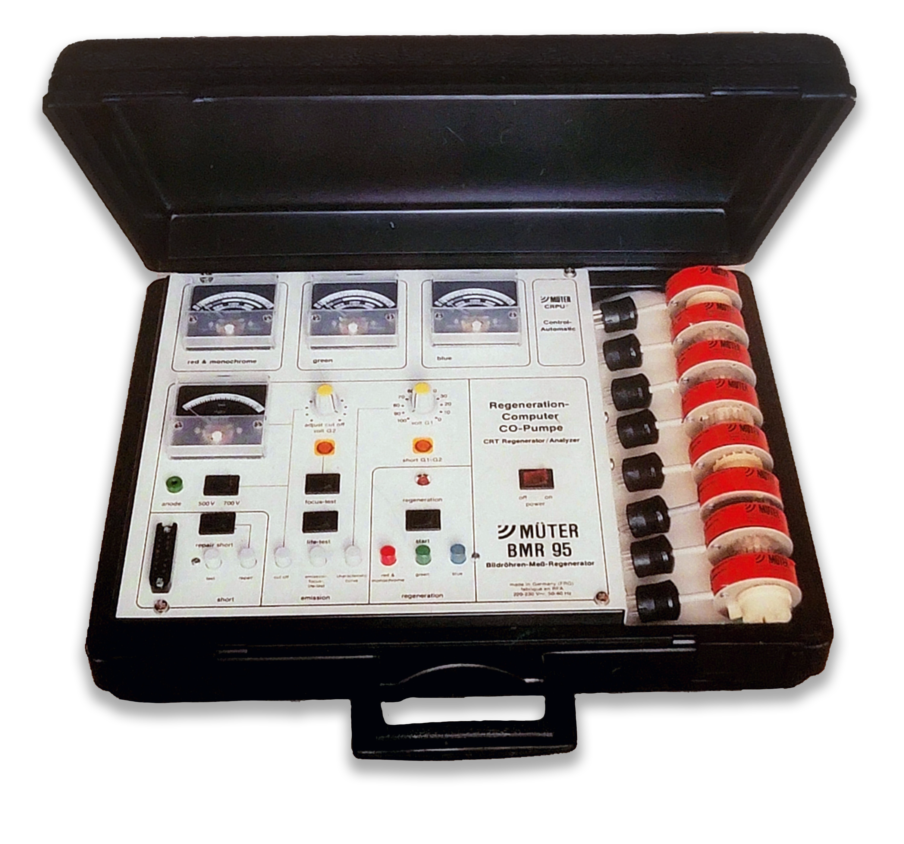
Overview
Müter testers are largely unheard of in the USA but I believe they have a strong use-case for anyone who is serious about CRT restoration. I have found that they are remarkably good at rejuvenating Trinitron tubes without destroying them - even the PVM tubes. This may just be due to the flash-ex procedure they came bundled with (which you can actually do with a B&K 467/490 or CR7000 plus a DIY adapter - more on that below) but the only other rejuvenator I've ever seen that didn't kill a Trinitron "on impact" or shortly after was a CR-7000 on its reactivate setting - and this Müter is WAY more effective. The owner's manual gives comprehensive and easy-to-follow instructions on the rejuvenation features and all other aspects of using the tester, so I won't go over that in this guide.
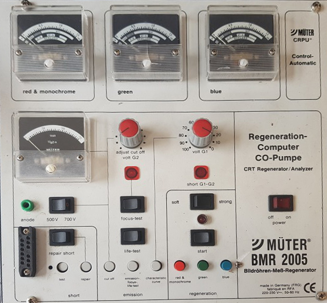
The Müter BMR 95 and 2005 are nearly identical despite being released 10 years apart. The only change to the 2005 model was the addition of a "soft" rejuvenation mode (described below). This guide will be written primarily for the 95 model but will have a description of the additional 2005 rejuvenation mode. There are older versions such as the BMR-90 BMR-85, and 80 but I do not recommend those testers as highly. They are missing some features from the newer ones, such as CPU-controlled rejuvenation and the fourth Vu meter display that measures current.
Müter testers are named after their creator, Ulrich Müter. There are more than 163 special adapters that were being sold directly from Ulrich himself well into the early 2000s - I've been told you can still get a hold of him for questions or spare adapter stock, although the business does not really exist anymore. In their heyday the testers could be special-ordered (or converted) to run off of USA mains voltage, however these testers were primarily sold in Europe and those will require 220v step-up conversion to be used elsewhere. I have not run across any with the USA transformer conversion yet - the only reason I know it was possible is because the user manual makes mention of it.
Key Features
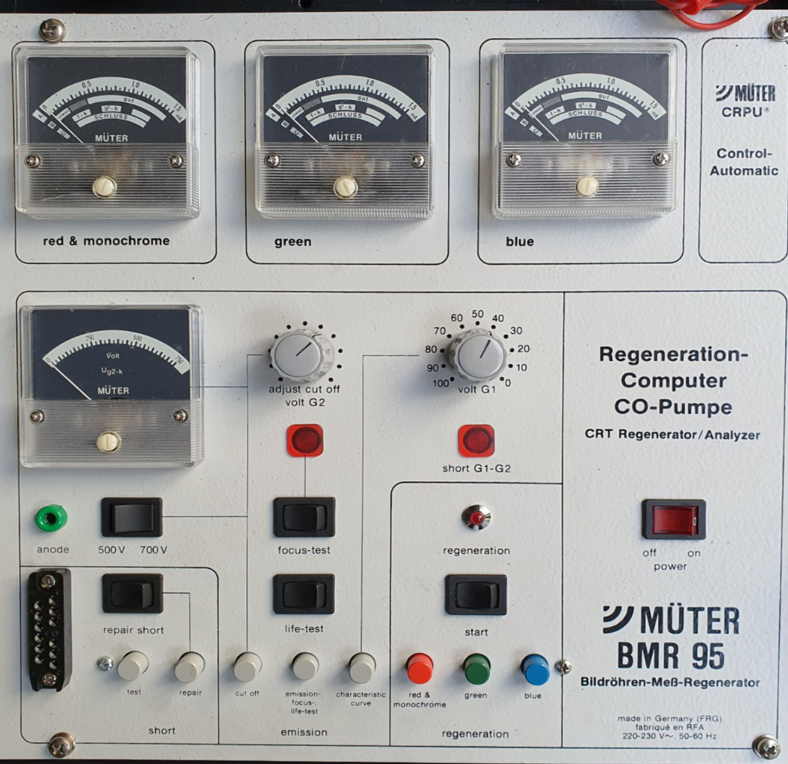
In addition to the standard/expected features of a CRT Tester, the BMR 95 & 2005 have these additional key features:
- Remarkable ability to bring dead Trinitron tubes back to life
- CPU-controlled rejuvenation process that measures current, temperature, time, and more.
- Patented FLASH-EX process for removing gas and other contaminants from within the picture tube to prevent flash-over damage to the electron guns after rejuvenation.
- G1 Characteristic Curve performance measurement (see owner's manual)
- Advanced tube life expectancy tests that pair with charts in the owner's manual
- Range of supported filament voltages (determined by the adapter cable & socket adapter): 0.53 | 0.7 | 1.6 | 2 | 2.7 | 4.7 | 6.3 | 8.4 | 9 | 11 | 12.6 volts
- Self-limiting G1 Shorts Clearing (current only flows if there is actually a short, no damage can occur to a tube without shorts)
Additional BMR-2005 feature:
- "Soft" rejuvenation mode. This mode "operates with shorter pules" and is only helpful in the following cases: a) If the connection between the cathode plate and the cathode mount is loose, regeneration will cause the cathode plate to become detached from its mount, b) if the getter of a tube is in poor shape, it fails to fix the gas which is released during rejuvenation. The gas atoms and molecules remain in the vacuum, and when the tube has been in operation for a short time, recombine with the cathode surface, which leads to a huge reduction in cathode emissions, c) if the tube cathode is overheated by the rejuvenation process, the cathode mass evaporates, shrinking to a remainder which cannot be rejuvenated; rejuvenation will eventually destroy it.
Buyer's Guide
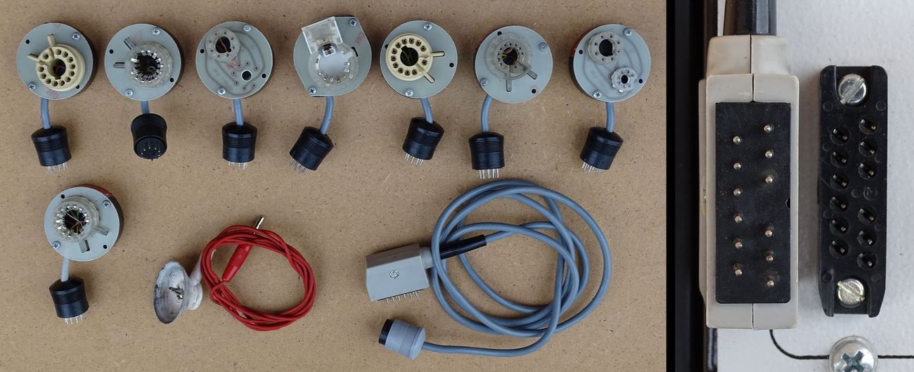
There is a cable that you must check for before buying a BMR tester (see righthand image). It is the socket adapter cable that connects between the 12-pin socket on the lower-left corner of the tester and the 8 pin socket adapter. This is the standard 6.3v cable that you will need to use the tester at all. The plug it uses is not an available off-the-shelf part, so a DIY solution would take some considerable work.
You may also notice a rubber suction cup with a wire included with the tester - this is an anode connector with a banana plug on the other end. The intended use is to drain the CRT of any remaining high voltage - personally I don't suggest using it over something safer like a high voltage probe.
Ideally your tester should come with the owner's manual and a CRT socket booklet, but PDFs will be provided here if you didn't get any. The last pages of the manual are a schematic in case you need to make any repairs.
In order to use this tester outside of Europe you must connect it to a step-up transformer. If you live in the USA I personally recommend buying this one but any will do. It does not rely on 50Hz phase.
Manuals & Set-up Charts
Schematics are available on the last page of the owner's manuals. The owner's manuals are multi-lingual, keep scrolling until you find your native language.
- BMR-95 Owner's Manual - scan coming soon
- BMR-2005 Owner's Manual
- FLASH-EX Brochure & Manual - scan coming soon
- Tube Lookup Booklet (Updated 2018)
- List of all currently known Müter adapter pinouts (language is German)
You can also use our tubes database to look up which socket adapters work with a given tube.
Maintenance Checks
Other than cleaning dirty potentiometers I am not aware of any common maintenance that needs to be done on these testers yet.
Socket Adapters
Müter Adapters
There are at least 163 adapter configurations that were made and sold by Müter. Most BMR testers on the market only come with a small handful. You can make your own using the pinouts and documents below, but if you are looking for OEM ones, the most common ones you'll want are:
- 808 (CR-23)
- 816 (CR-31)
- 828 (CR-36)
- 861 (CR-70)
FLASH-EX
The FLASH-EX is another socket adapter that is used specifically for post-rejuvenation to remove any gas or contaminants from inside the electron gun assembly to reduce the risk of flash-over damage. Flash-over damage seems to typically be the killer of Trinitons post-rejuvenation... it happens when rejuvenation blasts off conductive contaminants from the electron guns which then land on the grids of the tube and short things out. Then when you power the tube it causes a blast in the neck and kills one of the electron guns or the tube filament. Trinitrons seem especially susceptible to this because of their compact inline unified electron gun arrangement - everything is so close together that its very easy for small particulate to cause shorts.
Interestingly, the flash-ex process does not require a Müter tester, or any tester at all. It's just a straight connection from the tube socket to the tube ground, which means anyone can do the flash-ex process even if they don't have Müter equipment. If your Müter tester did not come with a FLASH-EX adapter, it is very simple to make one yourself. The only purpose of the adapter is to join every pin of the tube to a common output wire, which then connects to the tube's DAG (ground) strap. See the brochure above in Manuals & Set-up Charts for illustrations.
In order to flash-ex your tube, first you connect the correct Müter socket adapter to the tube (e.g. 808, 816, etc). If you don't have the socket adapter, you can make one yourself using a spare socket from a neckboard or online arcade store - or, alternatively, you can use EZ Hook Mini-grabbers to connect up to each pin of the tube. You must connect to every single pin, including the G3/Focus pin (and H-STAT on Trinitron tubes). If you don't have all pins connected, you will hear a hissing noise from the tube during the flash-ex process and it will not work.
After connecting the socket to the tube, you connect the Müter adapter cable to your socket adapter, and then to the flash-ex adapter, which then clips to the tube's ground strap. If you do not have a flash-ex adapter and are using a custom adapter or clip leads, make sure all of your connections lead to the tube ground strap for this step.
Ensure that you have laid the neckboard (which still has all its wires connected leading to the chassis) aside in a safe position where it will not conduct with any metal objects / parts or touch you.
Next, you power the CRT on normally as if you were going to use it. This will energize the tube with high-voltage so the flash-ex process can begin. NOTE: If your CRT does not turn on with the neck board disconnected, you cannot do the flash-ex process. Some CRTs require beam current (IK) feedback from the tube in order to run, and so with the neck board disconnected it senses a failure and cuts the high-voltage output. You can theoretically get around this by connecting your tube's anode to a DIFFERENT CRT chassis which is capable of running without a neckboard connected - just make sure the new chassis does not exceed the maximum anode voltage for the tube, otherwise you will cause x-ray emissions and expose yourself to radiation. Generally two tubes of the same size are capable of accepting similar anode voltages, but Y.M.M.V. and you have been warned.
Now wait 15-30 minutes while the flash-ex process happens. You may hear occasional pops and sizzles from the neck (or see sparks inside) as contaminants move around but this should subside eventually. If you hear constant noise or see constant arcing you should stop the process and return to the Müter tester to check for shorts. Otherwise, if you continue to hear occasional noises or see sparks as your time nears 30 minutes, continue waiting another 15-30 minutes. If it still continues, turn the TV off and let it cool for 30 minutes, then restart this step again.
After you finish the flash-ex process you can turn the CRT off and disconnect all of the cables you added. Start by disconnecting the Müter socket from the neckboard - then you are safe to disconnect the clip lead from the tube ground strap. Finally, reinstall the neckboard onto the tube.
Socket Pinouts
All currently known Müter adapter pinouts are in this document.
Thank you to this page for some images used.